
Development of a touch keyboard for your devices
- DIY or Do It Yourself
In this article I will describe the process of developing a touch keyboard that you can use in your devices. Such a keyboard is not difficult to assemble, because... There are no mechanical parts, and what it lacks in mechanical feedback it makes up for in elegance of use.
During the development of one project, I needed a comfortable keyboard with 8 buttons. I decided to resort to a well-known approach - to implement capacitive sensors.
I have already described the physical theory in my article about the device-souvenir, which I felt when it was taken in the hand (http://habrahabr.ru/blogs/DIY/111627/)
The principle remains exactly the same, the only difference is in the implementation - not two microcontroller pins are used, but one.
First, a video of what we will strive for:
Step 1: Circuit Design
The circuitry of the sensors has changed slightly, due to the fact that it is necessary to use only one microcontroller leg per sensor, and not two. However, if you don’t mind the extra legs, then you can leave everything as before.
The order in which the sensor is polled will be slightly different. Initially, a log is applied to pin PD0. 0.
Thus, current flows from the power supply through the megaohm resistor and flows into the pin. If the sensor was charged, then the current from it will also flow into the PD0 pin.
At the time of polling, we switch the pin from output to input (braces are disabled!). At this moment, the pin goes into a high-impedance state, with a resistance of the order of several tens (or even hundreds) of MOM. The current in the direction of the pin practically stops flowing and begins to flow towards the sensor. As soon as the sensor is charged to a voltage above the log level. 1, this microcontroller input will show one.
By measuring the time that has passed from the moment PD0 is transferred to a high-impedance state until log 1 appears on it, we can conclude that the sensor capacitance has changed, and therefore, catch the moment of touch.
Structurally, the sensor is a rectangular contact pad 10x10 mm, but in fact its shape is practically unlimited; you can make circles, snakes, divide them into segments and sectors - in general, enter information in any form.
Below is a photo of the finished PCB. The board is custom-made, but making one at home is also not difficult. When using breadboards, a piece of foil fiberglass glued on top of the board can act as a sensor.
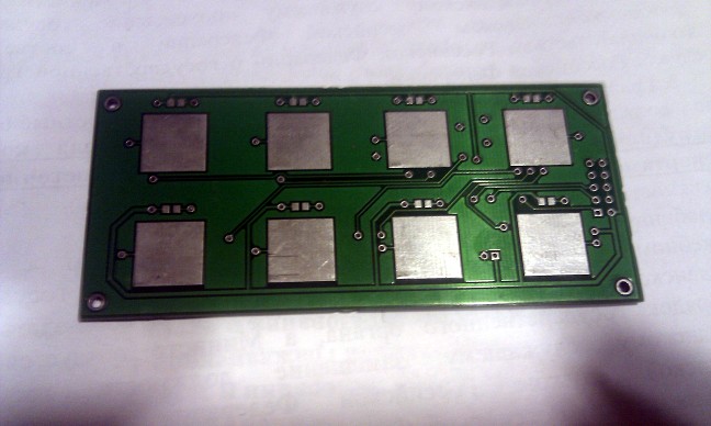
Above each sensor there is an SMD diode to indicate pressure.
All this is controlled by the ATMega88 microcontroller, clocked at 20 MHz.
Thus, the output from this keyboard can be whatever you need and whatever you want. In my case, SPI was convenient (I flashed and tested without disconnecting from the programmer, and this bus was already enabled in the device), but you can use the UART, I2C, built into the mega along with SPI, or use the USB software implementation from ObjDev. Yes, in fact, it is possible with hardware, such as an FTDI USB->UART converter.
The final diagram (screenshot from Altium) is presented below.
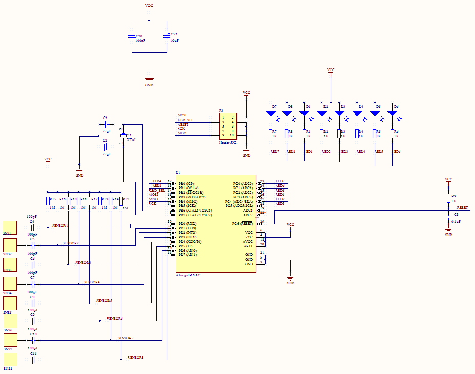
Again, nothing complicated, nothing superfluous - a mega circuit that clocks it, a pair of power smoothing connectors, a connector for programming/connection, 8 diodes and 8 sensors.
What’s interesting: the distance at which the sensor can feel the hand depends on the bit capacity of the timer, its frequency, as well as the resistance through which the sensor is connected. This is explained simply - a faster timer will be able to detect smaller time intervals, and in the absence of galvanic contact with the sensor, the charging time is significantly reduced. 20 MHz of the mega and its 16-bit timer are enough to confidently detect a touch through a layer of plastic (plexiglass) of about 1 mm.
You can slightly overclock the mega and slightly increase the resistance, but it is better not to get carried away with this - the stability of the overclocked mega is not guaranteed, and too much resistance can equalize the charge current with the leakage current, which will make the sensor forever inactive.
Be that as it may, normal operation is quite enough to cover the sensors with a thin piece of plastic. The ideal option would be to spray a conductive coating on the glass, but I did not have much opportunity to experiment in this direction.
Step 2: Code
In principle, everything has already been described above, but for some clarity I will give the project code.
#include